Source: Advertisement,
Official Guide - New York World's Fair, 1964 Edition, Time-Life
Books, publisher
|
|
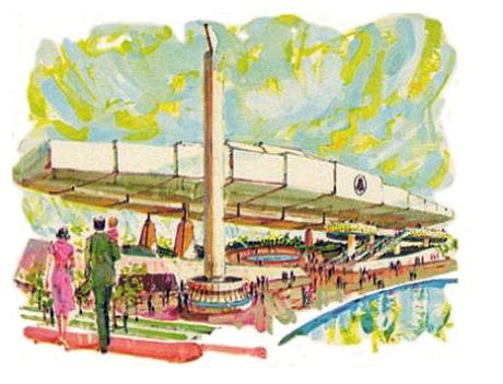
- IT'S FOR YOU -- The Bell System Exhibit of
- Communications Past, Present
and Future
|
|
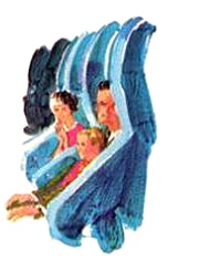
- ..Visit the Bell System exhibit and be
our guest as upholstered arm chairs, each equipped with its own
speaker, take you on a moving tour of the history of communications--one
of the theatrical highlights of the Fair.
- ..Then, see for yourself the new technology
that is now bringing people ever closer together, making business
more productive and efficient, strengthening our Nation's defense.
You and your children can play ingenious electronic games designed
to demonstrate these advances.
- ..This exciting exhibit is easy to find.
It's in the heart of the Fair at the head of the Pool of Industry.
Come in today--it's all for you!
|
|
- (Right) At the Bell System
exhibit, you'll ride in individual easy chairs through the main
presentation--see and hear a dramatic show in modern comfort.
|
|
 |
|
 |
|