- Source: Postcard Published by Dexter Press, West Nyack, N.Y.
- Source: Postcard Published by Manhattan Post Card Publishing Co., New York, N.Y.
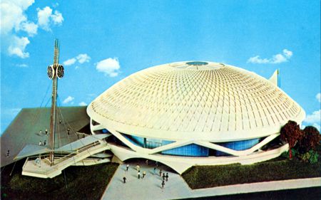 |
- General Electric Progressland
- Official Postcard
- No. 74195-B
- Dexter No. N/A
- Manhattan No. W-22
 |
|
- Source: Postcard Published by Dexter Press, West Nyack, N.Y.
- Source: Postcard Published by Manhattan Post Card Publishing Co., New York, N.Y.
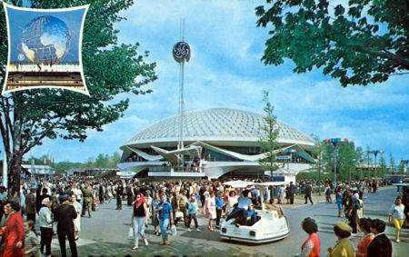 |
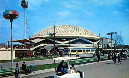
- General Electric Progressland
- Official Postcard
- No. 87184-B
- Dexter No. WF-65
- Manhattan No. W-68
 |
|
Source: Postcard Published by Dexter Press, West Nyack, N.Y.
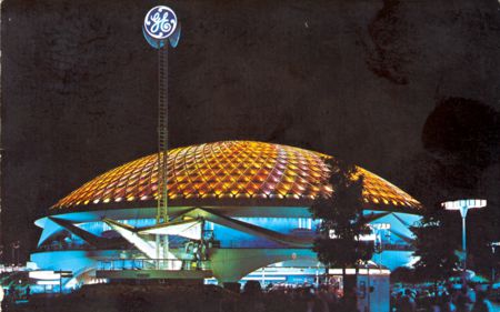 |
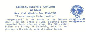
- Night General Electric
- Official Postcard
- No. 91861-B
- Dexter No. WF-112
 |
|
- Source: Postcard Published by Colourpicture Publishers Inc. (Plastichrome)
 |
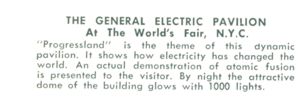
- General Electric Pavilion
- Unauthorized Postcard
- No. WF404
-
 |
|
|