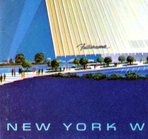
Booklet: Lets Go to the Fair and Futurama
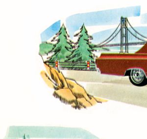
ClIck the Hand
to go to
Booklet:
Then, The Fair