Source: US World's Fair Commission
Report, December 1960
|
| NEW YORK WORLD'S FAIR 1964 -
1965 CORPORATION |
| INTERIM REPORT OF THE EXECUTIVE COMMITTEE
OF THE FAIR |
| TO THE PRESIDENT AND CONGRESS OF THE UNITED
STATES |
| SUGGESTING FOR
CONSIDERATION A PLAN FOR A PERMANENT |
| FRANKLIN NATIONAL
CENTER OF SCIENCE AND EDUCATION |
| TO HOUSE THE
UNITED STATES EXHIBIT AT THE FAIR |
|
|
|
INTRODUCTION
|
In order to facilitate action
on the vitally important United States Exhibit at the World's
Fair, the executives and directors of the Fair invited distinguished
consultants to prepare a plan of federal participation which
would provide a focal center, symbolize the basic theme and purposes
of the Exposition, serve as a guide to other American exhibits
illustrating the progress our nation has made, and serve as the
nucleus of a permanent Franklin National Center of Science and
Education paralleling in this field the area of culture represented
by the Lincoln Center for the Performing arts at Lincoln Square.
All signs point to a superlative
Fair at Flushing Meadow. It seems certain that exhibitors, domestic
and foreign, industrial and cultural, will send to us the very
best they have to offer. It becomes vital then that in the worldwide
competition of ideas and practical accomplishments, our central,
pivotal, national exhibit shall not, through lack of imagination
and financial support, be outclassed by others. The United States
Government exhibit should present graphically and convincingly
in impressive surroundings the immense strides we have made under
our free democratic system.
The distinguished servants whom
we consulted on this plan were:
- In Science:
- -Dr. Detleve W. Bronk, President of the
Rockefeller Institute and of the National Academy of Sciences-National
Research Council.
- -Dr. John R. Dunning, Dean of Engineering,
Columbia University
- -Dr. Lloyd V. Berkner, President, Associated
Universities, Inc.
- -Dr. William L. Laurence, Science Editor,
The New York Times, Chairman
-
- In Education:
- -Dr. John H. Fischer, Dean, Teachers College,
Columbia University
- -Dr. John W. Gardner, President of the
Carnegie Corporation of New York and of the Carnegie Foundation
for the Advancement of Teaching
- -Dr. Fred M. Hechinger, Education Editor,
The New York Times
- -Dr. Joseph E. Johnson, President, Carnegie
Foundation for International Peace
- -Dr. George N. Shuster, Past President,
Hunter College, Chairman
We have taken the liberty of
including in this interim report very preliminary graphic illustrations
of the plan we suggest and a rough estimate of cost.
It is unnecessary to add that
the location and character of this key federal exhibit are of
urgent importance because they affect and influence many other
features of the Fair which are advancing rapidly.
|
FRANKLIN NATIONAL
CENTER OF SCIENCE AND EDUCATION
SCIENCE EXHIBIT
|
Your committee is unanimously
agreed that the United States exhibit "involving primarily
our scientific accomplishments and our expectations for the near
future" should be the outstanding exhibit at the Fair. It
should be the finest of its kind, fully commensurate with the
greatness of America, not only as the country in which free men
attained the highest technological development and the highest
standard of living of any nation in history, but also as the
country in which science has made possible the evolution of a
free society in which every man achieved the highest dignity
and stature as an individual with the greatest opportunities
ever for the full development of his physical, intellectual,
spiritual and creative potential.
Not only has science made possible
in the United States the highest form of a free society, in which
every individual has an equal opportunity to realize to the fullest
extent all the innate potentialities of his endowment, it is
now playing the central role in the all-important task of defending
our free society against the greatest threat in its history.
A science exhibit officially sponsored by the leading nation
of the free world must make it clear to all the world that in
the great war of ideas we are now engaged, our greatest defensive
weapons are not atomic and hydrogen bombs but the mind of man
functioning in a climate of individual freedom.
While a United States science
exhibit should, understandably, involve our scientific accomplishments
it should not limit itself merely to our own accomplishments.
Fundamental scientific discoveries, upon which our great technological
achievements are based, have largely been made by scientists
of the free Western democracies, mainly Britain, France, Germany,
Italy and the Scandinavian countries. Our modern industrial civilization
began with the steam engine, invented by an Englishman, who made
use of basic laws of mechanics discovered by Galileo, an Italian,
and Newton, an Englishman. Newton's fundamental discoveries have,
in fact, laid the foundation for all the great contrivances of
the Machine Age. The principle of electromagnetic induction,
which made possible the dynamo and ushered in the Age of Electricity,
was discovered by Faraday, an Englishman. Another Englishman,
Sir J. J. Thomson, discovered the electron, the basis of all
the marvels of electronics -- radio, television, radar, automation,
02
|
rocketry, satellites, etc. Roenrgen,
a German, discovered the X-ray, one of the most powerful tools
to penetrate the mysteries of matter, as well as a powerful weapon
in the diagnosis and treatment of disease. Becquerel, a Frenchman,
discovered radioactivity, which opened the door to the Atomic
Age. Rutherford, an Englishman, discovered the nucleus of the
atom, citadel of the material universe, while another Englishman,
Chadwick, discovered the neutron, which opened the way to nuclear
fission, discovered by Otto Hahn, a German. Pasteur, a Frenchman,
discovered the bacterial origin of infectious disease and laid
the foundation for modern immunology, which revolutionized medicine
and public health. Fleming, an Englishman, discovered penicillin,
which opened the way for the antibiotics that have so far saved
more lives than were lost in both world wars. Mendel, an Austrian
monk, discovered the laws of heredity and laid the foundation
for modern genetics.
It is these fundamental discoveries,
made by men seeking knowledge for the sake of knowledge per se,
without an thought of its possible practical application, that
have opened the way for all our own scientific accomplishments,
which in turn, have made possible our way of life. Hence it is
obvious that a United States exhibit must, first of all, be a
history of ideas, showing how the inquisitive mind of man, given
full scope in an atmosphere of intellectual freedom, has, over
the centuries, and particularly since the advent of free institutions,
managed to make nature yield some of her most important secrets,
and how these triumphs of man's free mind have, in turn, made
it possible for all free men, and particularly the American people,
to harness the forces of nature to build a better life in an
environment vastly more suitable for man's needs, material, as
well as spiritual.
All the aforementioned fundamental
discoveries and many others in the fields of astronomy, physics,
chemistry, biology, genetics, geophysics, medicine, agriculture,
metallurgy, etc. upon which all our modern technological civilization
is based, should form important parts of the United States exhibit.
By taking advantage of all modern techniques of presentation
-- color motion pictures, television, transparencies, revolving
stages, with prominent scientists taking part in the demonstrations,
either in color
|
|
|
motion pictures or in person,
such exhibits could be made not only highly instructive, but
highly dramatic and entertaining as well.
There is no greater thrill than
that of the naked mind of man, with or without simple tools,
challenging nature to yield up some of her important secrets
and coming out triumphant after overcoming apparently insuperable
obstacles. The intellectual and spiritual exaltation, the religious
awe, that must have overcome Newton when he discovered the Law
of Gravitation, the ecstasy experienced by Einstein when he discovered
the principle of relativity (he was so overcome that he actually
took to bed for two weeks); the joy of Pierre and Marie Curie
the night they first saw the eerie light of radium in the abandoned
cadaver shed, after four years of back breaking labor, to take
but a few examples at random, could be made to live again in
the minds and hearts of the spectators at the exhibit, through
dramatic re-enactments of the original scenes.
Such exhibits will dramatically
demonstrate the following fundamental points:
- All modern technology has its
origin in fundamental discoveries made by inquisitive minds seeking
knowledge of nature.
- While pure science seeks only
knowledge, without any thought or practical application, every
scientific discovery eventually leads to far-reaching technological
developments for the improvement of man's lot on earth. Technology,
in turn, gives science new tools that make possible further fundamental
discoveries.
- All major discoveries in science
have led to further enhancement of the democratic way of life.
- Conversely, the democratic way
of life creates the best environment for the creative mind. This
is particularly true in the development of science and technology.
Without in any way resorting
to propaganda, the exhibit, as outlined, will make it clear that
not one of the major discoveries mentioned has come from either
Czarist or Communist Russia, or from Nazi Germany, or from any
other country without democratic institutions. The only major
technological development in Nazi Germany, the V-2 -- the first
practical rocket -- was based on principles developed by the
American, Robert Goddard, whose basic ideas were also lifted
bodily by the Russians
03
|
in the development of their sputniks.
In fact, all of Russia's technological progress is based on fundamental
scientific discoveries and technological developments made in
the free world, their technological development being largely
based on the technology of the United States.
All the aforementioned lead your
committee to the following conclusions:
- The United States Scientific
Exhibit should be the finest of its kind, exceeding in scope
the outstanding examples of equivalent institutions anywhere
in the world -- such as the Deutsches Museum in Munich or the
Palace of Discovery in Paris. It should, in fact, aim to become
one of the wonders of the modern world, fully representing the
spirit of America and commensurate with its greatness as the
leader of the free world. Properly planned, it could serve as
an expression of our faith in the future, as a potent weapon
in the war of ideas. In the present fateful struggle between
the concepts of a free society and totalitarian enslavement we
cannot afford second best.
- Such an institution must, obviously,
become a permanent part of our cultural heritage. It must be
housed in a monumental building that in itself would represent
one of the finest structures of its kind in the world, one that
would stand as a symbol of the modern free world in the same
manner as the great cathedrals of Europe symbolized the aspirations
and the faith of their builders and of the peoples of their day.
- We believe that such an exhibit,
and the structure in which it is housed requires a minimum of
seven acres, including exterior landscaping. A central location
is desirable as the United States Science Exhibit should be at
the center of the Fair, the hub from which all other exhibits
radiate. Such a central location, we believe, will enhance the
value of, and interest in, all other technological exhibits to
be presented by our leading industrial organizations, the technologies
of which are the results of basic discoveries in science. The
United States Science Exhibit would serve as the background that
will make all these industrial exhibits more understandable,
and hence more attractive.
|
|
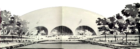
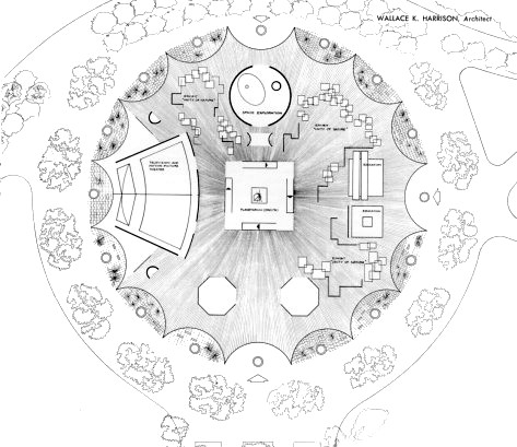
[Top: Artist's
conception of the proposed Franklin National Center of Science
and Education/Federal Pavilion at the 1964/1965 New York World's
Fair as designed by Wallace 9 Theater (left), Space Exploration
area (top) and a Planetarium (center). Display area called "Unity
of Nature" surrounds these major exhibit areas. And an area
for Education was reserved (right).]
 |
 |
|
The structure housing the United
States Exhibit should in itself be a most dramatic exhibit, a
dynamic symbol of the world of the future, showing the creative
mind of America at its best in one of its most original aspects.
The preliminary sketches for the proposed building were prepared
by Wallace K. Harrison.
After careful consideration,
your committee has come to the further conclusion that a United
States Science Exhibit of the dimensions outlined above would
require an appropriation by the Federal Government of $30,000,000
-- $20,000,000 for the building and $10,000,000 for the exhibits
it would house.
The institution on Flushing Meadow
must not be a museum of static displays, but a living dynamic
institution, a great cultural center, designed to instruct, to
enrich and to inspire all those who visit it, young and old,
university graduates and those of no more than a grammar school
education, It should instruct and at the same time entertain.
This great Center of Science and Technology, as we prefer to
call it, should be the equivalent of a great National Theater,
in which the leading actor is the human mind, groping and struggling
through the ages to learn the secrets of nature and to make man
at home in an orderly universe.
The Center would thus be above
all a revolutionary type of educational institution as well as
a new form of entertainment. Like a great repertory theater,
it should schedule special programs, daily or weekly, so that
a visitor having once come to it will want to visit it again
and again and will tell his friends to do likewise. It would
serve as a model for similar institutions in all other cities
throughout the country as well as in other parts of the world.
It could become a major attraction for conventions and tourists,
one of the showpieces of America.
As already stated, the Center
should take advantage of all modern techniques of presentation,
color motion pictures, television, revolving stages, etc. Motion
pictures in color should present in dramatic form the story of
the major discoveries of the fundamental laws of nature upon
which all our modern technology is based. The emphasis in all
these should be not on the "what?" but on the "how?",
the manner in which an idea emerged, not infrequently over the
course of centuries or millennia.
06
|
The exhibit should aim to give
the average person an outline of man's knowledge of the universe,
the infinite and the infinitesimal, the living and the non-living,
and how this knowledge was acquired. The motion pictures and
lectures by eminent scientists should serve to provide the background
for actual demonstrations showing the mind of great men in action.
These demonstrations should be
associated with personal participation on a do-it-yourself basis,
with the visitor himself performing some of the crucial experiments
that represent landmarks in the growth of ideas. The visitor
could be taught to weigh the earth, the moon and the sun; to
measure the velocity of light; and to determine on his own the
distance from the earth to the sun. Repeating the experiment
of Galileo, the visitor would rediscover for himself the law
of falling bodies; he could discover helium in the sun and determine
what other elements the sun is made of; he could repeat Faraday's
simple experiment that led to the Age of Electricity, and the
epoch making experiment by Hertz, in which he created the first
man-made electromagnetic wave, which ushered in the age of radio,
television and radar. These are only a few examples in which
the average person could be initiated into the fellowship of
the great discoverers through the ages.
Rather than being lost in a maze
of detail, the exhibit should stress the unity of nature and
the fundamental laws that govern it. It should be built around
several great general exhibits, all interrelated. One of these
should give the visitor a comprehensive view of the cosmos at
large, the universe of stars, galaxies and supergalaxies. Another
should give the story of the solar system and of the earth. The
story of matter and energy should be the subject of a third.
Another general exhibit should be devoted to the story of the
evolution of life on earth and the possibility of its existence
elsewhere in the universe. The nature of life and how it functions,
with emphasis on human development and physiology, should be
the subject of another. An exhibit showing how a humble monk,
Gregor Mendel, observing his peas in his garden, discovered the
laws of heredity operating throughout the entire realm of life,
from the lowest of bacteria to man, should be the starring point
for an exposition of the story of genetics.
All these great exhibits, however, should merely
|
|
|
serve as the background for the
story of America's contribution to science and technology, from
colonial times to the present. It should show how, building on
the discoveries of the past, the American creative mind transformed
a virgin continent into a New World which offered the greatest
opportunities for the individual to grow in freedom and to attain
the highest standard of living in history.
The exhibit should constitute
a great pageant of the great names in American science and invention
-- Franklin, Eli Whitney, Joseph Henry, Fulton, Morse, Bell,
Willard Gibbs, Michelson, Millikan, Edison and Tesla, to mention
but a few. It should show America's great contributions to the
development of the telegraph and the telephone, the automobile,
radio, television, and radar; the airplane, the helicopter and
the jet plane; its contributions to the science of nutrition,
to medicine and to surgery, to agriculture and transportation,
to the harnessing of great rivers, such as the Niagara and the
St. Lawrence with scale models of these giant dams.
Two of the major exhibits of
American technology should, of course, show our country's outstanding
contributions to the Atomic Age and the Age of Space. The atomic
exhibit should show the highlights of the great secret wartime
development that brought the Atomic Age into being. It should
show, among others, a model of the first nuclear reactor built
in the squash court at the University of Chicago, the first atomic
power plant in history. It should be climaxed with an actual
experimental swimming pool type of nuclear reactor, of the type
shown by the United States at the United Nations Conference on
the Peaceful Uses of Atomic Energy in Geneva in 1955. Such a
reactor is absolutely safe and is highly spectacular. The exhibit
should also illustrate the great promise of atomic energy as
a vast new source of energy for industrial power, and as a most
important tool in agriculture, biology and medicine, which promises
to play a major role in the conquest of disease and the prolongation
of life.
The exhibit on the Space Age
should, first of all, provide a clear explanation of the fundamental
principles of the rocket and the principles that maintain a satellite
in its orbit. It should display models of the various American
satellites placed in orbit, their instrumentation and their purpose.
It should also
07
|
leave room for any new satellites
and new discoveries that will be made after the exhibit had been
set up.
In addition to providing a comprehensive
outline of scientific discoveries and technological developments
up to the present, the Fair should also provide a glimpse of
the immediate and the more distant future. It should show how
atomic energy promises to give mankind everywhere an abundant
source of energy for an abundant life, and how that will serve
as a vital factor in bringing peace to the world. It would show
mankind entering an era in which most major diseases will be
eliminated and the average lifespan will be significantly increased.
It should also show that, within the next two decades or so,
scientists hope to solve the problem of harnessing the fusion
energy of the hydrogen bomb as a limitless source of industrial
power, with the oceans of the world providing an endless source
of fuel.
Lastly, it should provide a glimpse of what further explorations
of outer space will bring in the future. Such a glimpse will
make the onlooker aware that we stand on the eve of some of the
greatest discoveries ever made, discoveries that may open vast
new horizons for mankind.
The exhibit as a whole must avoid giving the impression that
science and technology are purely materialistic. Science is the
outgrowth of the spirit of man, of his desire to know, to seek
the truth. Its technological fruits serve to make man free from
exhausting physical labor, to enable him to cultivate his spiritual
and creative powers, in short, to make him free. An understanding
of science should therefore give us faith in the future, for
science, by fostering the free mind, is the greatest enemy of
totalitarianism. The old maxim, "And ye shall know the truth
and the truth shall make you free" is still as valid as
it ever was
- Respectfully submitted
- DETLEV W. BRONK
- JOHN R. DUNNING
- LLOYD V. VERKNER
- WILLIAM L. LAURENCE
- Chairman
|
|
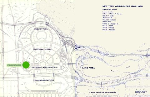
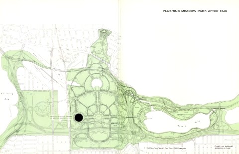
[Top: Site Plan
of the 1964/1965 New York World's Fair showing the proposed location
of the pavilion. Bottom: The Franklin Science Center would
be retained as a major feature of the post-Fair Flushing Meadows
Corona Park as illustrated in this diagram.]
|
 |
ADDENDUM TO THE
REPORT OF THE SCIENCE COMMITTEE
EDUCATION EXHIBIT
|
As stated in the report of your
Committee on the United States Science Exhibit, the National
Center of Science would "be above all a revolutionary type
of educational institution as well as a new form of entertainment."
On further consideration, and
in the light of the valuable report of the Committee on Education
headed by Dr. George N. Shuster, and including Dr. John H. Fischer,
Dr. John W. Gardner, Dr. Fred M. Hechinger and Dr. Joseph E.
Johnson, it appears that the educational potentialities of such
a Center would be greatly enhanced by the incorporation of a
special exhibit that would tell in dramatic form, largely
through color motion pictures and closed circuit television,
the inspiring story of the development of the American educational
system, from the beginning to the present, with a glimpse into
the future.
Such an exhibit would not
require a special building, as one large hall, in the form
of an attractive and spacious auditorium, equipped with a modern
stage and screen and decorated with murals giving the highlights
of the story of education in America, would adequately serve
the purpose. Such a Hall of Education should form an integral
part of the Science Building. The Center could thus be named
the "Franklin National Center of Science and Education."
The educational section of the
Center should avoid any semblance of static museum-type exhibits.
The development of the educational system in America is one of
the glories of our land, a story of great human interest that
can be told in colorful and dramatic sequences in which the highlights
covering a period of more than three centuries could be reenacted
and made to live again. The story should tell how from the very
beginning the "things" our forefathers "longed
for, and looked after was to advance learning and perpetuate
it to our posterity." It should tell not only the American
people but the peoples from all parts of the world who will visit
the Fair, and in the years to come, that the ideal of universal
education for all, and not only for the privileged few, was fostered
in our country from the beginning; that this ideal became a keystone
of our democratic way of life, which gives every individual an
equal opportunity to develop to the fullest possible extent all
the innate talents within him. It should show that only in America
has this ideal been fostered, and is still being fostered,
12
|
not for the purpose of creating
robot-like servants of the State, but to give every individual
an equal opportunity to rise to his highest dignity as an individual;
to give life a higher meaning; to inspire to the fullest measure
a devotion to the highest values of existence; to instill in
every citizen love of God, of country and of his fellow men.
The spirit of American education,
that might well be expressed in an inscription on one of the
walls of the proposed Hall of Education, could best be illuminated
by the inspiring passage from New England's First Fruits, published
in 1643, telling the story of the founding of Harvard College
in 1636, a bare sixteen years after the landing of the Pilgrims.
"After God had carried us safe to New England, and wee
had builded our houses, provided necessaries for our liveli-hood,
rear'd convenient places for Gods worship, and settled the Civil
Government; One of the next things wee longed for, and looked
after was to advance learning and perpetuate it to our Posterity;
dreading to leave an illiterate Ministry to the Churches, when
our present Ministers shall lie in the Dust.
"And as wee were thinking and consulting how to effect
this Great Work, it pleased God to stir up the heart of one Mr.
Harvard (a Godly gentleman and a lover of learning, there living
among us) to give the one half of his Estate (in being in all
about 1700 pounds) toward the erecting of a Colledge; and all
his Library; after him another gave 300 pounds. Others after
them cast in more, and the publique hand of the State added the
rest; the Coledge was, by common consent, appointed to be at
Cambridge ( a place very pleasant and accommodate) and is called
(according to the name of the first founder) Harvard Colledge."
This inspiring story could well be dramatically re-enacted
in a color motion picture, to be written by one of our leading
dramatists. The film would show the Pilgrims in solemn conclave
at a Town Meeting which may well have followed the funeral of
one of their ministers. They would be shown discussing the need
for the advancement and perpetuation of learning, revealing their
"dread of leaving an illiterate ministry," and their
despair because of the lack of funds with which to accomplish
their purpose, when a young minister among them, John Harvard,
rises to announce his magnificent gift.
|
|
|
The story could then go on to
tell the early struggles of the young college for survival, how
the students paid their tuition with products of the farm --
cheese, milk, eggs and vegetables, which the faculty lived on.
It could show actual classrooms of the 17th Century, the methods
of teaching, student life, their games and their pranks. The
story could untold the role played by Harvard in the Revolutionary
War, in the Civil War, in World War I and II. Leading actors
could re-create some of the great teachers and personalities
of Harvard during its three centuries, making them live again
in their classrooms. Interwoven through the story should, of
course, be the landmarks showing the growth of Harvard from a
tiny "Colledge" of one small building to one of the
world's great institutions of learning with outstanding graduate
schools in Medicine, Law, Business, the Arts, the Sciences and
the Humanities.
Similar inspiring, intensely
dramatic stories could be told of our other great universities
-- Yale, Princeton, Columbia, to mention but a few. Many of these
dramatizations already exist. For example, during its recent
fund drive, Harvard produced a splendid motion picture, "From
the Age that is Past," shown so far only to a limited audience
of alumni, which should prove highly interesting to the public
at large.
Another dramatic and colorful
story could be told of the development of our great Land Grant
colleges and universities showing President Lincoln signing the
Land-Grant Act in 1862 and explaining its purpose; the development
of our great State Universities; the establishment of our great
institutions of learning for women; the world famous institutes
of technology, such as M.I.T. and Caltech; our great research
centers, such as the Rockefeller Institute; the unique Institute
for Advanced Study at Princeton; and our gigantic National Laboratories,
serving groups of universities, at Brookhaven, N. Y., Oak Ridge,
Tenn.; and Argonne, near Chicago.
By means of closed circuit television,
the visitor at the Center would be permitted to enter classrooms
in several of our leading universities, showing education in
action. He could be made a participant in some of the sudents'
extra-curricular activities, watch rehearsals and actual performances
of their dramatic societies, debating teams, glee clubs. he could
sit in at a typical "bull-session" among undergraduates
and made to feel as one of them.
One of the special features of
the education exhibit could be a re-enactment of some of the
memorable football games
|
of the past, bringing back to
life, or restore the youth of, some of the legendary names in
football history. This feature of the exhibit should, of course,
show present day athletic activities, illustrating the fact that
American education is designed to meet the needs of the whole
man, body, mind and spirit.
A major part of the exhibit should
be devoted to a dramatic presentation of the development of the
elementary school, the high school and the kindergarten, with
living subjects playing their respective parts in the proper
environment. This group of exhibits, all in color motion pictures,
should bring back to life the original red school house, with
all the trimmings. It should show the teachers and the children
in the dress of the period, and the manner in which the three
R's were taught. It should graphically depict how this little
red school house gradually developed over the years into the
modern elementary school and high school. These exhibits also
should show typical classrooms in action, with living actors
playing the part of the teachers and real children acting as
the pupils. Whenever possible actual modern classrooms should
be entered by means of closed circuit television.
One of the major aims of this
exhibit would be to illustrate the development of the art of
teaching from its crude beginnings to its modern advanced techniques.
This could be done by showing classrooms at various periods in
our history and the methods used in teaching certain subjects.
The exhibit could be climaxed with a present day version of
the meeting of the Pilgrims that led to the founding of Harvard.
In the modern version we would have (in color motion picture)
a group of distinguished educators, including the presidents
of a number of our leading institutions of learning, expressing
their fears for the future and affirming once again that "the
things we long for, and look after, is to advance learning and
perpetuate it to our posterity." In this sequence should
be outlined, in the words of the educators, the great problems
now facing American education, stressing the fact that we are
now engaged in a fateful struggle for survival that requires
the training of our best minds, through a system of universal
education designed to meet effectively the great challenge of
our day.
Respectfully submitted
WILLIAM L. LAURENCE
Chairman, Science Committee
|
|
|
|
December 5, 1960 |
|
|
Webmasters
note...
On March 15,
1958, a meeting was held in Washington D.C. that included representatives
of the US Congress and the scientific community. "The consensus
of the meeting was that if the backers of the Seattle Exposition
[of 1962] were serious about having a large popular
science exhibit, the scientific community would eagerly support
them. However, it was emphasized that the exhibits must deal
with science not in terms of technology, but as an adventure
of the mind, as man's effort to understand the universe, and
must appeal to the general public rather than the spiritualist."
-- U.S. Science Exhibit, Seattle World's Fair, Final Report,
March 15, 1963.
It is curious
then that the New York World's Fair proposed to the Federal Government
that they sponsor a major Science Exhibit at their World's
Fair. Exposition organizers knew that planning had been underway
for the Science Exhibit in Seattle for over two years when they
made their proposal on December 5, 1960. In fact ground had already
been broken for the U.S. Science Pavilion in Seattle four months
earlier and construction was proceeding.
Why the duplication
of theme? The United States pavilion at the Brussels World's
Fair of 1958 also relied heavily on Science to attract crowds
and show off U.S. superiority in the Cold War. Did Cold War attitudes
in the early sixties dictate New York should follow it's predecessor
Fairs in using Science as a weapon in a war of exhibits? Did
New York wish to take advantage of the popularity of Science
to ensure crowds; thinking that a Space Age Fair without a Science
Center as a base was doomed to fail? Was it a way for the Fair
to get the Federal government to pay for the Hall of Science
they desired for post-Fair Flushing Meadows Park? Or were they
simply afraid of being out-classed by a much smaller city's Fair?
|
|